Understanding Layer 2 stretch in Nutanix Disaster Recovery-as-a-Service
By Bharad Sabnis
Purpose
The infrastructure for Nutanix Disaster Recovery-as-a-Service (DRaaS) supports a tenant cluster and a production virtual private cloud (VPC) for each customer. Customers generally have production VMs running in their on-premises cluster, which is connected to the DRaaS VPC using an IPsec tunnel. This is used by the DRaaS workflow to replicate on-premises production data.
During a disaster recovery situation or while running disaster recovery tests, VMs will failover from on-premises to the DRaaS cluster. When this occurs, all VMs in one subnet of an on-premises network (e.g., 192.168.10.0/24) usually failover to DRaaS. If the customer chooses to preserve the IP, VMs in DRaaS come up with the same IPs as on-premises (e.g., 192.168.10.0/24 network).
In this type of disaster recovery situation, customers can choose which critical VMs are replicated to DRaaS. But in those cases, on-premises VMs cannot communicate with VMs in DRaaS.
Why this is the case
The reason behind this is that Nutanix DRaaS advertises the subnet 192.168.10.0/24 over eBGP to on-premises while the on-premises VPN gateway will have already learned that route locally. Because local routes have shorter administrative distances, no user VMs from on-premises can communicate with DRaaS. This is a Layer 3 routing conflict that can be solved by using the Layer 2 stretch feature.
This blog will cover:
- The basics about Layer 2 stretch.
- The journey of a visible extensible LAN (VXLAN) packet in a Nutanix DRaaS environment.
What is Layer 2 stretch?
Layer 2 stretch enables VXLAN over IPsec on Nutanix VPN gateways to stretch an on-premises subnet to DRaaS. VXLAN technology is a Layer 2 overlay scheme over a Layer 3 network. VXLAN uses MAC address-in-user datagram protocol (MAC-in-UDP) encapsulation to extend Layer 2 segments across a Layer 3 segment. This basically means the Layer 2 packet gets a VXLAN header applied, then the frame is encapsulated into a UDP IP packet and sent over a Layer 3 network.
When the feature is enabled, the VPN controller plugs NICs corresponding to the stretched subnet into the DRaaS VPN gateway and the on-premises VPN gateway. As a part of the subnet stretching, the VPN gateway configures a VXLAN interface, creates a Linux bridge, and adds the extended subnet interface and the VXLAN interface to the bridge.
The DRaaS VPN gateway uses Virtual Tunnel Interfaces (VTI) to establish eBGP over IPsec for on-premises cluster connectivity. As a result, the VTI interface serves as a transport link for VXLAN communication so that the VXLAN traffic can be encrypted and tunneled through IPsec.
Nutanix recommends using Layer 3 routing over the Layer 2 stretch implementation. If preserving IP addresses for universal virtual machines (UVMs) is not a requirement, it is a best practice to use Layer 3 routing. In that case, an on-premises network (e.g., 192.168.10.0/24) is failed over to DRaaS with a different subnet (e.g., 172.16.30.0/24), which eliminates routing conflicts.
Prerequisites
- The on-premises environment must be running at least PE AOS:5.19.x and PC AOS:2021.3.x.
- The feature is compatible with only VYOS gateway appliances and the minimum required is 4.0.x and above.
- IPsec and eBGP must be established between the Nutanix DRaaS and on-premises Nutanix VPN gateways.
- Requires two static IPs from the subnets to be stretched. This will later be assigned to the additional Ethernet interfaces of the Nutanix VPN gateways.
- General limitation: The VPN gateway and Layer 2 subnet extensions are only supported on ESXi-standard vSwitch port groups. Distributed vSwitch is not supported.
Journey of a VXLAN packet in a Nutanix DRaaS environment
To explain how a VXLAN packet traverses a stretched network, this blog will cover a few VXLAN terminologies, the MTU and TCP-MSS settings, and an ARP resolution scenario when VM details are not learned by the VPN gateway. Here is the setup after the feature is enabled.
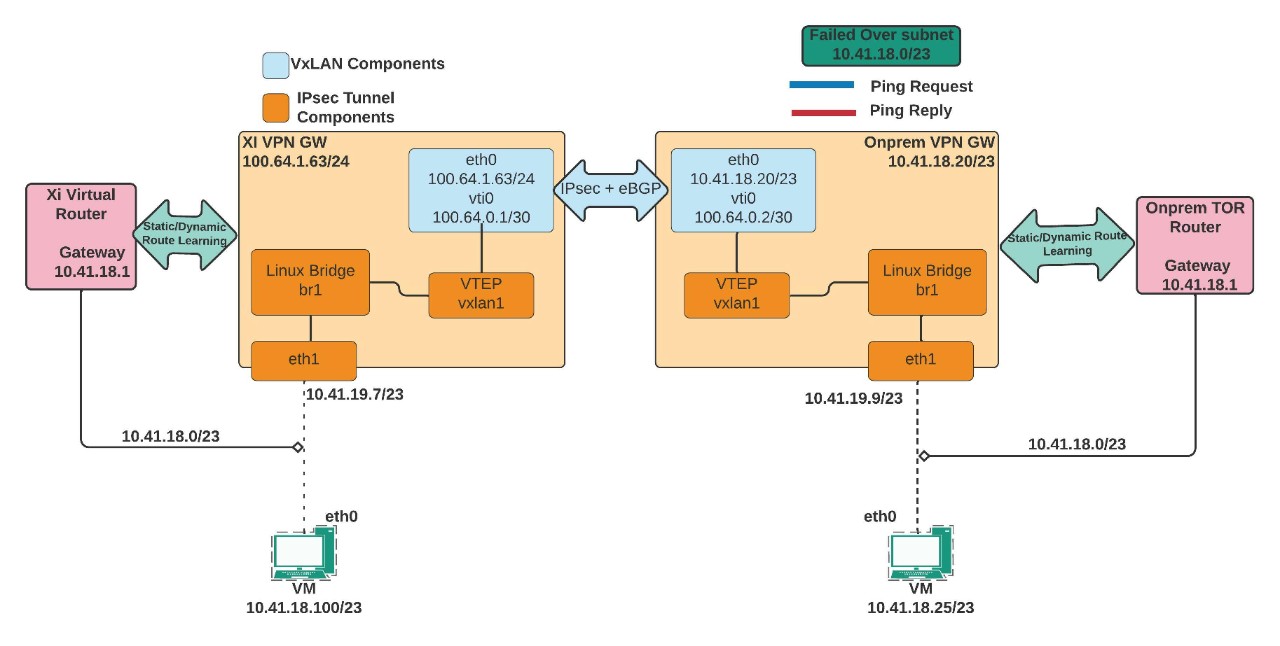
VXLAN components and their importance
- The significance of the eth1 interface: The eth1 interface is part of the Linux bridge of the VPN gateway and is required to relay ARP requests from on-premises to DRaaS and vice versa. When an on-premises or DRaaS VM tries to reach a remote VM this interface picks up the broadcast frame (ARP Request) and relays it through the Linux Bridge br1, VXLAN1 interface, and over the IPsec tunnel.
- VXLAN Interface: VXLAN interfaces perform encapsulation and decapsulation, known as VXLAN tunnel endpoints (VTEPs). The VTEPs encapsulate a Layer 2 frame with a VXLAN header, a UDP segment (port number 4789), and then add an IP packet.
- VXLAN Network Identifiers (VNI): The VXLAN header maps Layer 2 VLAN numbers to VNI (VXLAN Network Identifier - Range: 4096 to 16,777,215). This is how Layer 2 to Layer 3 mapping is kept intact. For example, 192.168.10.0/24 may belong to VLAN 20 on-premises and VLAN 100 on DRaaS. However, encapsulation and decapsulation of the VTEPs occur with a common VNI between the two VPN endpoints.
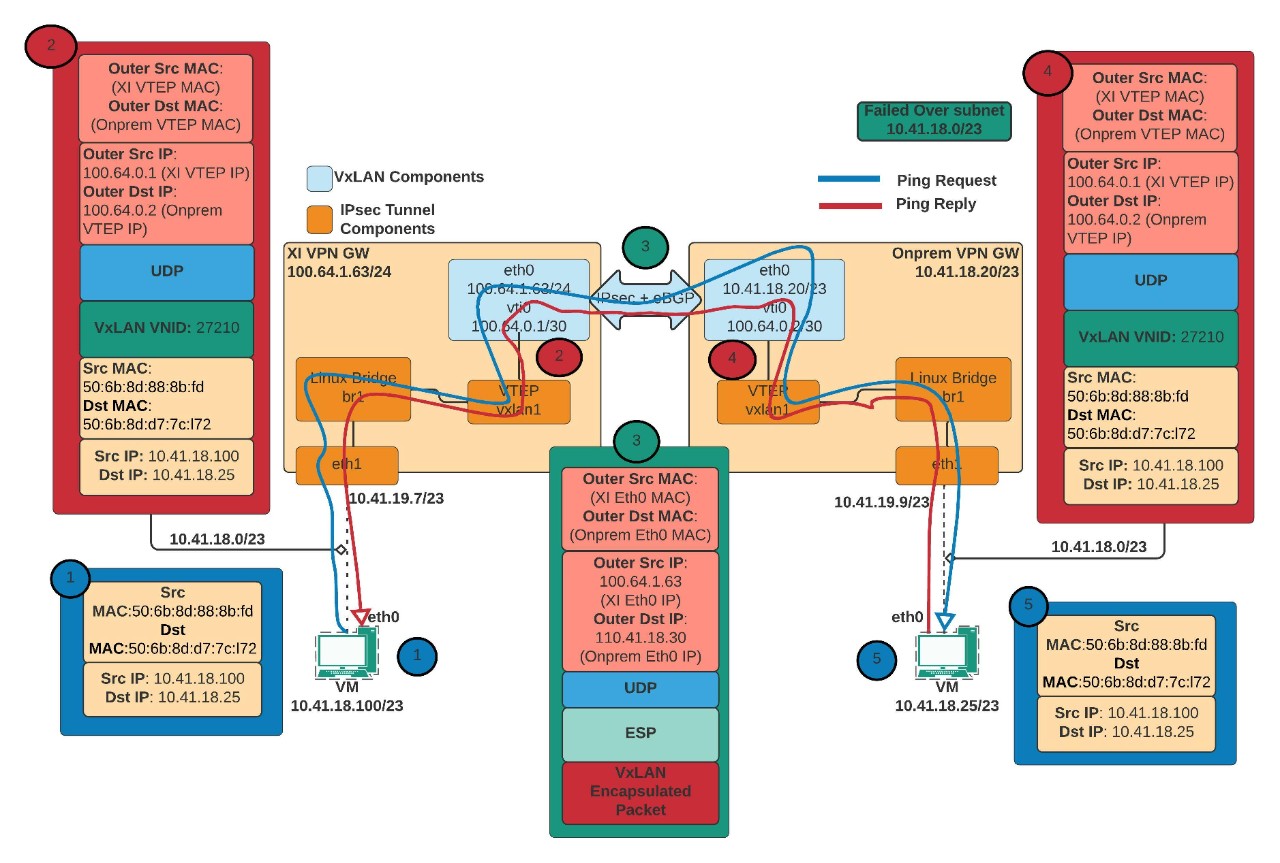
In this scenario, here’s what happens when subnet 10.41.18.0/23 fails over and recovers in DRaaS:
- When a ping request from DRaaS UVM (10.41.18.100) to on-premises UVM (10.41.18.25) is initiated, the UVM may not have an ARP entry in its cache. Consequently, it broadcasts the ARP request that enters the DRaaS VPN gateway through the eth1 interface (10.41.19.7).
- Since the Nutanix DRaaS VPN gateway has no information about the on-premises UVM, the packet is given to br1 and then to the VXLAN1 interface.
- Before the packet reaches the VTI interface, the original Ethernet frame is encapsulated with a VXLAN header, a UDP header and an IP packet. The source and destination IPs are the VTI interface IPs.
- When the packet reaches the VTI interface, it is encrypted with an encapsulated security payload (ESP) header and an IP packet. The source and destination are the DRaaS eth0 IP and on-premises eth0 IP.
- The packet next enters the on-premises VPN gateway through the IPsec tunnel, the ESP header is removed/decrypted, and is given to the VXLAN1 interface. The VTEP (VXLAN1) interface decapsulates the UDP header, the VXLAN header, and hands it over to the br1. The br1 Linux bridge of the on-premises VPN gateway registers the DRaaS UVMs MAC address (source MAC address). From the br1, it is given to the eth1 interface and sent to the on-premises UVM.
- When the on-premises UVM receives this ARP request, it stores the DRaaS UVM ARP entry in its cache, and the ARP resolution for DRaaS UVM is complete. The on-premises UVM then sends the unicast ARP reply with its own source MAC address.
- Next, the on-premises UVM sends ping reply-packets, which reach the DRaaS UVM using the same path.
To illustrate the journey, this diagram shows the path and possible encapsulation of a VXLAN packet:
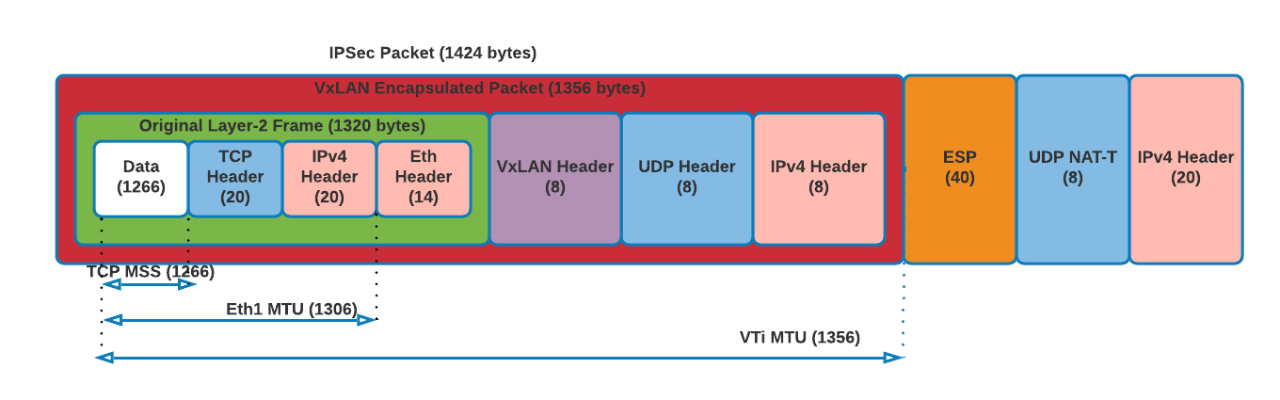
MTU and TCP-MSS
After all levels of encapsulation, the packets flowing through the IPsec tunnel between the NX gateway appliances will generally look like this:
- Ethernet frame received from Xi UVM at Xi VPN GW’s eth1 will be 1,320 bytes:
1320 = 1266 (data) + 20 (TCP header) + 20 (IPv4 header) + 14 (Ethernet header) - VXLAN interface encapsulated the above frame with VXLAN header, UDP header and IPv4 header making the packet size to 1,356 bytes:
- 1356 = 1320 (original frame size from (1)) + 8 (VXLAN header) + 8 (UDP header) + 20 (IPv4 header)
- VTI interface encrypts the packet and adds IPsec overhead with ESP header, UDP for NAT-T and IPv4 header making the size 1,424 bytes:
- 1424 = 1356 (original VXLAN packet from (2)) + 40 (ESP header) + 8 (UDP header for NAT-T) + 20 (IPv4 header)
When the VM from either side sends a packet with a size of 1,266 bytes, the packet after VXLAN and IPsec encapsulation would look like:
Scenarios to overcome
Controller VM subnet extension across clusters
This scenario assumes that DRaaS has the same subnet already created. Layer 2 stretch can be leveraged in a scenario where the on-premises controller VM (CVM) subnet needs to be extended to DRaaS. However, to stretch the subnet in this case, a few routes must be added.
- Log in to your Nutanix DRaaS portal and select Virtual Private Clouds.
- In the top corner, select the Production VPC > Select Routes tab and select Create Static Routes.
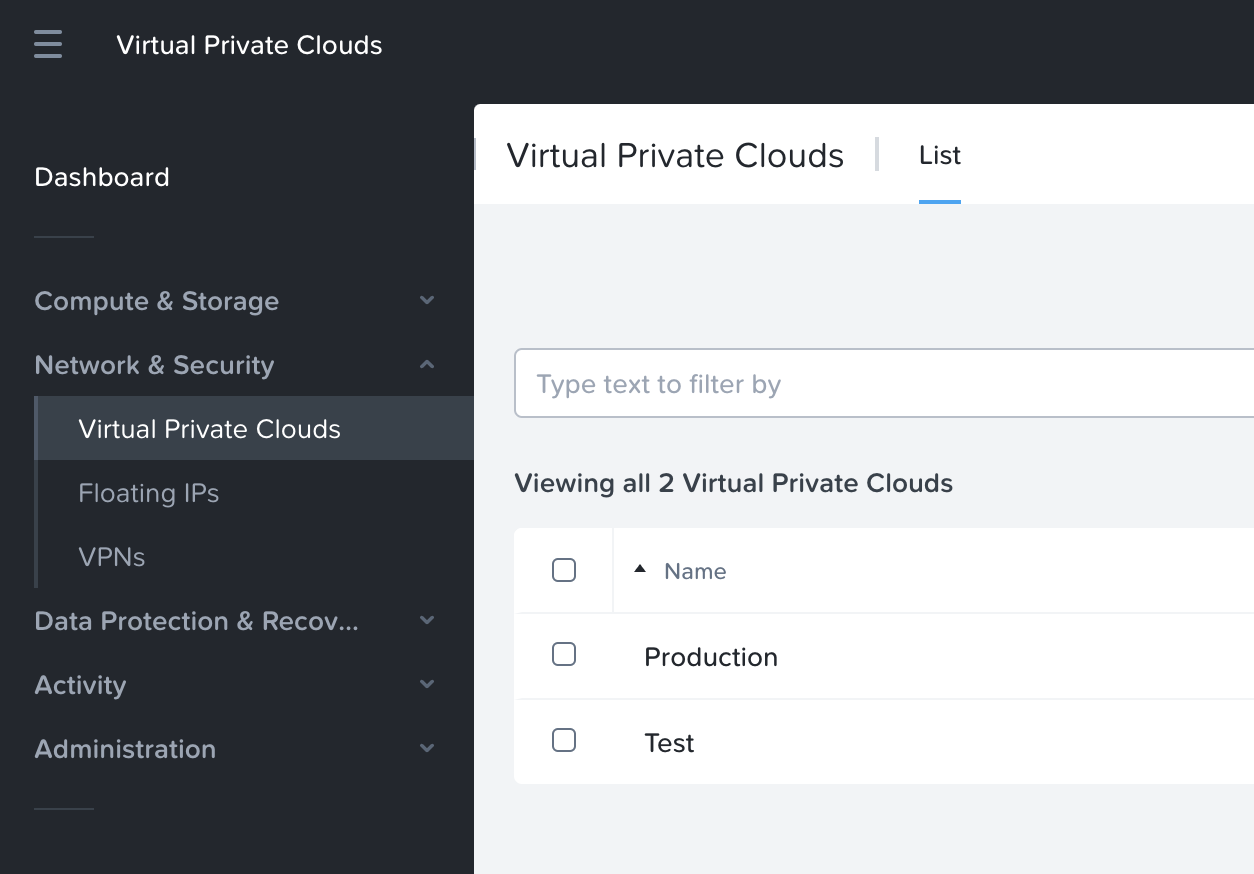
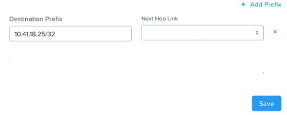
- Create a static route to the PCVM in the on-premises cluster alone.
- This is a requirement to restore the AZ connectivity between clusters as the subnets are in a conflicting state without the Layer 2 feature enabled.
- After the route creation, AZ connectivity will be restored, and the Layer 2 extension can be configured for the desired subnet.
Defining gateways of an extended subnet on Nutanix DRaaS
Nutanix recommends that all VMs on a particular site are configured to use the default gateway of the respective sites. For example, VMs running on Site 1 use the gateway of Site 1, and VMs running on Site 2 use the default gateway of Site 2. There are two ways to approach this.
DRaaS subnet has the same on-premises gateway
In a scenario where the DRaaS subnet has the same on-premises subnet gateway, DRaaS UVM can reach the extended subnet on-premises and all other subnets on DRaaS without issue.
But if the DRaaS UVM wants to reach a different subnet on-premises, a static route must be added on the DRaaS to the destination subnet on-premises. Similarly, when an on-premises VM in the extended subnet range tries to reach DRaaS UVM on a different subnet, a static route for the on-premises top-of-rack (TOR) switch must be added.
In case of a planned failover scenario, the failed-over VMs will honor the static route to reach the destination subnet. Reachability to other DRaaS UVMs in other subnets will occur without issue.
Xi subnet has a different gateway compared to on-premises
In a scenario where the DRaaS subnet has a different gateway than on-premises, a DRaaS UVM can reach the extended on-premises subnet and all other subnets on DRaaS without issue. If the DRaaS UVM wants to reach a different subnet on-premises, a static route to the destination on-premises subnet is required. The added static route is honored only by the UVMs created on DRaaS.
In a post-planned failover, a VM would carry the on-premises gateway information and would be able to reach all subnets on-premises. However, failed-over VMs cannot reach other subnets on DRaaS as the gateway points to on-premises. For this VM to reach subnets on DRaaS, the TOR switch on-premises should have a static route to the DRaaS destination subnet with next-hop of the on-premises VPN gateway’s VTI interface. The traffic path here will look like this:
Xi VM -> VXLAN/IPsec -> on-premises TOR router -> Static route pointing to on-premises VPN vti -> Xi VPN gateway -> VPC LR -> Xi dest subnet
The above scenario is ideal for customers who want to maintain the traffic flow of failed-over VMs from within the on-premises environment. An example would be if a customer wants to control internet reachability of failed-over VMs from an on-premises firewall.
For more information about configuring the Layer 2 stretch feature, refer to Layer 2 Virtual Subnet Extension (on-premises and DRaaS cloud services).